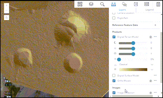
ArcGIS Ortho Maker features a dedicated viewer for displaying project data and products. The Ortho Maker viewer is similar to the portal's Map Viewer Classic, with a streamlined user interface designed for working with your project data and products. It supports a variety of standard basemaps and allows you to display your own services as a basemap.
The Ortho Maker viewer is integrated into your project workflow, where project data and products are displayed as your project progresses from setup to block adjustment to product generation. For example, immediately after project setup, the flight path and exposure location of your image collection are displayed on a basemap with the Project pane. When ground control points (GCPs) are loaded into the project, they are displayed in the Ortho Maker viewer, and a match point GCP collection viewer allows you to digitize match points corresponding to GCPs listed in the Adjustment pane. When products are created from the Products pane, they are displayed in the Ortho Maker viewer as they are produced.
Ortho Maker viewer toolbar
The Ortho Maker viewer toolbar contains six tools for displaying and working with your data and products.
| Viewer tool icon | Viewer tool label | Description |
|---|---|---|
| Basemap Gallery | Select from a gallery of standard basemaps, including an image basemap. |
| Layers and Legend | Open the Layers pane, where you can turn layers on and off; load reference feature data or maps from web services; and enhance layers in the Ortho Maker viewer. |
| Find Address or Place | Type an address or location into the gazetteer to pan to its location on the world map. |
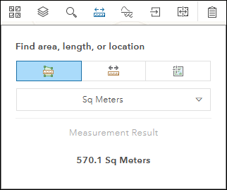
| Measure | Measure linear or area features on your map or products in the units of your choice, or get the map coordinates of locations. |
| Volume Calculation | Calculate the volume of material added or removed from an Area of Interest. |
| Download products | Download products from the map viewer in GeoTiff format. |
| Swipe Layer | Interactively compare layers beneath the layer being swiped. |
| Ortho Maker processing log | View the processing logs for your image collection, block adjustment, and generated products. |
Click any of the tools on the toolbar to activate it. The tool is highlighted to indicate that it is activated, It will remain activated until you deactivate it by clicking it again.
Note:
A handy shortcut to view the pixel value for a specific imagery layer such as a DEM product: press Ctrl+mouse hover.Layers and Legend
The Layers and Legend panes list all the layers available in your project.
The types of layers include GCPs, flight feature data such as image footprints and flight path, products and images, and custom feature and raster map services. Click the image enhancement button  next to each product and the Image Collection layer to change the rendering of the layer. Images can be enhanced using adjustments to brightness, contrast, gamma, and transparency. A color ramp can also be applied to single-layer raster layers.

Note:
You can load a feature layer service or raster layer service into the Ortho Maker viewer by specifying the URL.
Mensuration
You can measure 2D objects visible in your raster layers. Supported measurement types include polygon for area, polyline for multiple-segment lines, and a point location. Click the measurement type to display the choices for measurement units.

With the measurement type active, click vertices comprising your object of interest and double-click to end the measurement. The measurement result will be displayed for the last object measured.
Volume Calculation
Cut-and-fill is an operation in which the elevation of a landform surface is modified by the removal or addition of surface material. The Volume Calculation map tool summarizes the areas and volumes of change from a cut-and-fill operation. By using the digital surface model product and an area of interest (AOI) with a given base type, it identifies regions of surface material removal and addition.
Refer to Cut-and-fill volume calculation for details about how to calculate cut-and-fill material volume.


